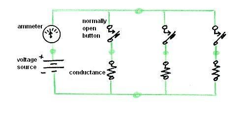
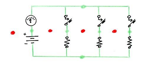
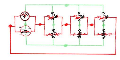
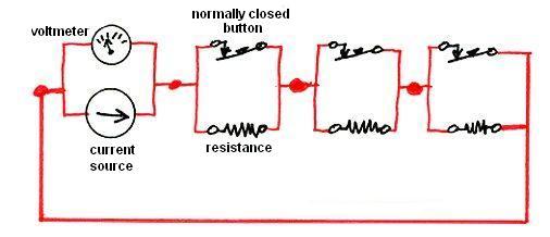
 How did I come to be an electrical engineer? It was a bit of an accident. But then, so are a lot of things in life. When I applied to MIT, I didn't know exactly what I would major in, although I was pretty sure it would be something in either engineering or science. On my application, I selected physics, sort of by default. Note 1 At the end of my freshman year, I was still unsure about what I wanted to do. But in perusing the catalog, with its lists of prerequisites, I noticed that if I were interested in electrical engineering as a possibility, there was a course in the first semester of my sophomore year that I had to take. I believe it was called "Linear Circuit Theory", although it may possibly have been called "Introductory Circuit Theory". It was designated 6.01, or possibly 6.001 (my memory is a bit hazy on this). Note 2 I also saw that a new alternative was being introduced, called "Electrical Science and Engineering". It was electrical engineering, but with greater stress on the science underlying the engineering practice. It was considered to be a five-year program, leading to a Masters degree at the end of the fifth year. That idea sounded interesting to me. So in order to preserve my ability to follow an electrical engineering path, I decided to change my major from physics to electrical engineering. And since the "Electrical Science and Engineering" option sounded enticing, I decided to try that. This meant that my advisor would be Professor Hermann Haus. I made an appointment with Professor Haus, and after spending some time with me, he noted, "Well, with your grades, there's no reason for me to turn you down." It was at that point that I realized for the first time that I needed to be accepted into this program, which, it turned out, was only a single section of about 25 students. My first year grades had been very good, almost straight A's (the one exception had been a B in my first-term humanities course). The class designations for courses in this section simply added a "three" at the end, so "Linear Circuit Theory" for our special section was called 6.013 (or, again, possibly 6.0013). During my years in the program, it turned out that the special "Electrical Science and Engineering" section was generally taught by full professors, who were usually quite interesting and effective teachers. This was not always the experience of others in the MIT class of 1963. They were often taught by graduate student "Teaching Assistants", whose teaching ability was spotty, and there were many complaints about them. Note 3 Anyway, back to my very first class in electrical engineering, 6.013. Walking into the room, I saw at the head of the class Professor Ernst Guillemin, author of the large and expensive textbook I had already purchased, "Introductory Circuit Theory". Note 4 Professor Guillemin babbled on for most of the allotted time about reminiscences unrelated to the course material, eventually talking a bit about his teaching career. He then segued into a discussion of the pleasure it gave him when one of his students expressed an interest in teaching, and he told us that he would not, in fact, be our instructor for the semester. Actually, given the way he had been rambling on without touching at all upon the material we had come to learn, I wasn't terribly sad to hear this. Finally, Guillemin introduced a young man who had been leaning against the wall on the side of the classroom, whom I had taken to be a fellow student. This turned out to be someone named "Larry Black", who was in fact an MIT senior. In an unusual arrangement, Larry had been designated to teach our course. Professor Guillemin then left the room. As soon as he was out of earshot, Larry noted that we probably wouldn't use Guillemin's book, and we didn't need to buy it if we had not already done so (I had, actually). Larry proved to be a dynamic and engaging teacher, and his approach to the course material was highly mathematical. Early on, we were exposed to the concept of a circuit having a corresponding "dual" circuit, which I'll discuss at the end of this blog entry for those who want to delve into this material a little more deeply (using as an example the voting circuit I introduced in my last two blog entries, starting with Voting, and moving on to Schematics). We then got into some pretty heavy mathematics, at least for college sophomores. We first used matrices to solve some rather complex resistive circuits. Then, energy storage elements were introduced, the capacitor (condenser), which stores energy in the form of an electrical charge, and the inductor, which stores energy in the form of a magnetic field. With these components, circuits can exhibit complex behavior over time, such as damped or undamped oscillation. These were solved in their turn by introducing a mathematical technique called the "bilateral Laplace transform", allowing very complicated circuit behaviors to be solved by simple algebra (although using what are called "complex numbers"). It turned out that the professors overseeing Larry Black's curriculum objected to his teaching that portion of the course in this manner, because we had not in fact yet had sufficient calculus to really be able to understand the mathematics involved. Therefore, Larry was required to use a different approach in our classes, the same approach used in the regular sections of 6.01. But Larry wanted to do it his way, which he did by adding on additional evening sessions to allow him to teach the needed mathematics. These sessions were optional, but if I recall correctly, every member of the class attended them (it didn't hurt that Larry served doughnuts). Thus we got the material in both the standard way and Larry's way. I think it was Professor Marvin Minsky who once said, "You don't really understand something until you've understood it two ways" (or maybe he said "three ways"). Linear Circuit Theory, and particularly its mathematics, was so beautiful and elegant that I decided by the end of Larry's course that what I wanted to be was an electrical engineer. In the second semester of my sophomore year, having studied "Linear Circuit Theory", we went on to - (what else?) "Nonlinear Circuit Theory". The instructor started out by drawing a lot of graphs, which most of the members of the class (me included) assumed he was doing to give us a kind of visual feel for the material before launching into a full mathematical description. Thus, we took few notes, waiting for the kind of elegant mathematics we had gotten from Larry Black. Only after quite a few classes did it begin to dawn on us that Nonlinear Circuit Theory had no such elegant mathematics. It was rather a hodgepodge of special techniques, often graphical, but without much of a common theme. If I had started with that course, I never would have selected electrical engineering as my major. If you'd like a touch of the elegance of Linear Circuit Theory, I think all of my readers are capable of understanding the concept of the "dual" of an electrical circuit. You might be able to get a rough idea of what's being done just by scanning the pictures, and I'll include, directly over each picture, an "executive summary" in bold. I'll use as an example the "blackball" voting circuit I described in my last two blog entries, Voting and Schematics). Here it is, shown with only three resistors in the ladder, for simplicity:  More detail: where I previously showed on the left just a box representing a resistance-measuring meter ("ohmmeter"), above I've shown its two component parts: a "voltage source" (shown using the schematic symbol for a battery), and an "ammeter", which measures current flow (in "amperes", or more idiomatically, "amps"). These apply a voltage between the top and bottom sides of the ladder, and measure the current which flows as a result. For this discussion, it turns out to be better to characterize the resistors by their "conductance", where "conductance" is the reciprocal of the resistance. That's because as we push the buttons and connect additional resistors into the circuit, we can just add up the total conductance - each added resistor conducts the same amount of current. If all the switches are open (= no buttons pressed), no current can flow at all. The more voting buttons are pressed (switches closed), the more resistors carry current from one side of the ladder to the other, and hence the more current is drawn by the circuit overall. By measuring this current, the ammeter can determine how many buttons have been pressed (that is, how many resistors have been connected). I've labeled the switches above to indicate that they are "normally open" pushbuttons. "Normally open" means the switches don't allow current to flow if the button is not depressed. Depressing the button "closes" the switch, allowing electricity to flow through them. Calling them "buttons" means that they are "momentary", so that when the button is released, it pops back up and once again becomes "open". The little black triangle on one side of each switch symbol is supposed to represent the part of the button that gets pushed. I've done one more thing in the above diagram: I've drawn the wires in green, and put a dot on each "node" in the circuit. The "nodes" are the electrical connections between the circuit elements. Any point in the circuit connected to a dot by a wire is part of that "node". Watch this: with three more figures, I'm going to develop the "dual" of the above circuit, drawing the dual circuit in red. First, let's put a red dot (to represent an electrical node of the dual circuit) in every "mesh" of the original circuit diagram, a "mesh" being a hole in the diagram. This assumes that the circuit diagram is "planar", which is to say it can be drawn on a flat sheet of paper without the necessity of any wires crossing over any other wires. Note also below that the paper entirely outside of the circuit represents a "mesh" as well, so there is a red dot in that mesh, on the left side (but I could have put it anywhere outside the circuit):  Now let's draw a new circuit element in red across each of the original circuit elements, at a 90° angle, connecting them to the node inside the meshes on each side. Look at the diagram below, as this is easier to show than to describe in words:  Having done this, I need to take away the original diagram, leaving only the red "dual" diagram, so you can see it clearly. To further clarify it, I've changed the elements of the dual circuit back to black, although I left the wires red:  Note that each circuit element of the dual circuit is the "dual" of the original circuit element it was drawn over. A normally-open button turns into a normally-closed button. That is, instead of closing when you push the button, the switch opens when you push the button. The voltage source becomes a current source, and the ammeter (which measured current) becomes a voltmeter (which measures voltage). Thus the resistance measurement is done in a different way, by driving a known current into the circuit, and measuring the resulting voltage. We now have a different circuit, but which could have equally well been used as a voting machine - it performs the same function. In the original circuit (the first of the figures above, entirely in black and green), we had a parallel-connected collection of element pairs, each pair comprising a normally-open-switch and a conductance connected in series. In the dual circuit (just above, in black and red), we have a series-connected collection of element pairs, each pair comprising a normally-closed-switch and resistance connected in parallel. In the original voting machine, when no button is pressed, all the conductances are removed from the circuit, because the switch in series with each is open. Thus no current can flow (there is no conductance), and applying a fixed voltage to the circuit, the ammeter measures zero current. For each button that's pressed, a conductance is switched into the circuit, and as more buttons are pressed, greater and greater current is detected by the ammeter. In the dual version of the voting machine, when no button is pressed, all the resistors are removed from the circuit because the switch in parallel with each is closed. Thus current is shunted around the resistor (current takes the path of least resistance), and driving a fixed current through the circuit, the voltmeter measures zero voltage. Each button that's pressed, opening the switch, forces the current to go through a resistor, and as more buttons are pressed, greater and greater voltage is detected by the voltmeter. The fundamental duality of electricity springs from the duality of voltage (which is measured across two nodes) and current (which flows into a node and around the circuit in a closed loop). That's why in the dual, a mesh becomes a node, and a node becomes a mesh. Kirchhoff's Voltage Law states that the voltage summed around all the circuit elements in a mesh (in any loop, actually) is zero, and Kirchhoff's Current Law states that the sum of the currents flowing into any node is zero. All the transformations made in turning a circuit into its dual spring from the duality of voltage and current (that is, voltage-source ↔ current-source, node ↔ mesh, normally-open-switch ↔ normally-closed-switch, ammeter ↔ voltmeter, resistance ↔ conductance, and so on). The voting machine could have been built either way, and in fact I don't actually remember how it was done. But if I were designing it, I would have done it according to the original (green) circuit, not the dual (red) circuit. That's because in the real world, there's an asymmetry in the properties of real switches. Although an ideal switch will conduct no current at all when open, and will present zero impediment to current flow (zero resistance) when closed, real world switches are not ideal. Real switches will typically allow virtually no current when open, just like a theoretical switch (any current that does get across an open switch is called "leakage", and is usually miniscule). But when closed, a real-world switch often does present some non-negligible resistance to the flow of current, because it has physical contacts that can get dirty or pitted, or which simply don't have a very large contact area. As the well-known philosopher Lawrence Peter "Yogi" Berra once said (I've mentioned this quote before), "In theory, theory and practice are the same. In practice, they are not." I have no idea what happened to Larry Black. If my memory is correct, and he was a senior when he taught me in the 1960-1961 academic year, he should have graduated in 1961. But I can't find him in the on-line MIT alumni directory, and I've been unable to pin him down in any web search (although, of course, that's difficult to do when someone has a common name). But the elegance of Linear Circuit Theory, and his masterful presentation of it, were what got me into Electrical Engineering.
  Note 1: I was admitted to two colleges, MIT and Cornell. But I had applied to Cornell in the Department of Mechanical Engineering, and because of its history as a state "land-grant" university, Cornell had more restrictions on changing from one department to another. It might have been more difficult for me to change departments had I gone to Cornell, and so I would have been likely to have become a mechanical, and not electrical, engineer. My father had attended Cornell (class of 1935), and when I selected MIT, I asked him if he would be upset with me for turning down his alma mater. He assured me he would have no bad feelings about that. In those days, high schools put restrictions on the number of colleges students were allowed to apply to. In the Great Neck school system, this meant that I could only apply to a maximum of three colleges. My third application was to Harvard, which turned me down (given my high school transcript, with strengths only in science and mathematics, it was a real long shot). I think that in my youth, people were more accepting of authority. Can you imagine high schools these days trying to dictate how many colleges you can apply to? They'd be sued in a flash. Similarly, we meekly accepted censorship of our books and movies. [return to text] Note 2: MIT numbers its departments, its courses, and its buildings. For example, physics is course 8, electrical engineering course 6, and mathematics course 18. Since the electrical engineering department is course 6, all its course numbers start with a 6, followed by a decimal point. Typically, the introductory courses have numbers ending in "01", "02", "03", and so on. Thus the introductory physics courses, in sequence, would be 8.01, 8.02, 8.03, 8.04, and so on. There was a period of time when a double zero was used in these numbers, so that the introductory electrical engineering courses might be called 6.001, 6.002, and so on. I don't remember if that was the case when I started the sequence. When I was at MIT, course 6 was simply called "Electrical Engineering". It now is called "Electrical Engineering and Computer Science" ("EECS"), reflecting the fact that more than half of its students specialize in computer science. Now really, computer science belongs more in mathematics than it does in electrical engineering. There is nothing particularly electrical or electronic about the study of software, and the hardware aspects of computer design are quite specialized, and practiced by a relatively small number of people. But computer science started at MIT in the Electrical Engineering department, and it has remained there largely for historical reasons. The Electrical Engineering department, MIT's largest department, certainly won't give it up now. Some universities have an entirely separate department of computer science. [return to text] Note 3: I recall (I think it was in my junior year) that my friend Martin Schrage came to my classes in the mechanical engineering course "Dynamics", or in MIT-speak, 2.02 (pronounced "two-oh-two"). This course, because of its difficult mathematics, was sometimes referred to as "two-oh-screw". The graduate student teaching Martin's class was having trouble getting the material across, but Martin found the crystal-clear presentation of Professor Den Hartog to be far superior. I remember Den Hartog deriving the mathematics describing the behavior of gyroscopes one class session, covering the blackboard with equations, and working without notes. The gyroscope equation turns out to be pretty simple (after some simplifying assumptions are made), but can only be arrived at by plowing through some pretty hairy math - you can get an idea here. There's a very famous law of motion called "d'Alembert's Principle", first enunciated by the French physicist and mathematician Jean le Rond d'Alembert. Den Hartog one day brought in a copy of the original book by d'Alembert containing the principle, which was buried in the middle of a lot of other material. It was hard to make out, due to weaknesses in d'Alembert's mathematical notation. - he tried to explain in ordinary French concepts that would have been more precisely presented in a mathematical notation that he apparently didn't yet have. This was one of the first times that I started to realize the importance of good notation in making mathematics comprehensible. I got a second education in this area when trying to understand a particular passage in an economics text by Paul Samuelson. Although Samuelson was an MIT professor who was an expert in the use of analytical techniques in economics, his text books were written for a more general audience. I spent quite a bit of time trying to understand the concept of "Price Elasticity of Demand" ("PED"), which the author attempted to explain in English (without much success, I thought). I asked another student for help, and he simply said, "Read the footnote". The footnote reported that for those familiar with the Calculus, the PED could be defined as P/Q(dQ/dP), where Q is the Quantity of a good that the market will demand at a price P. For me, that explained it better than the entire page of text above it. [return to text] Note 4:
Introductory Circuit Theory, Ernst Adolph Guillemin, Wiley, 1953, 550 pages. Out of print, but used copies available from Amazon and other sources. [return to text]
 |